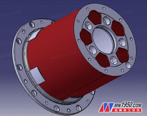
The material of the drive axle wheel reducer housing parts (see Figure 1) is generally QT550-5 or QT600-3 ductile iron. Due to the large number of holes in the machining of such parts, the service life of the drilling tool is required to be high. When the pores are actually processed, the edge of the main flank face of the integral alloy drill bit is severely chipped at the edge of the blade, which causes the overall alloy bit to be directly scrapped, and the tool life is reduced, resulting in a significant increase in the cost of the tool for the machined part. The increase in processing time leads to a significant increase in production costs during parts production. In this paper, the improvement scheme of the hole- cutting tool of the shell-type reducer housing parts is provided for the problem of chipping of the whole alloy bit.

Figure 1 Drive axle wheel reducer housing parts
Characteristics of drilling parts for shell parts
Drilling is a semi-closed cutting. Although the heat generated during the drilling process is transmitted from the chips, the workpiece, the
tool and the surrounding medium, the cutting heat generated during the drilling process raises the temperature of the drill bit. On the upper mechanical friction, the rake face, the flank face, the edge and the chisel edge of the ordinary integral alloy drill bit will cause different degrees of wear. The back angle of the edge is zero, the friction is large, and the corner angle of the corner is small. Due to the poor heat dissipation conditions, the parts required to be processed have high cutting speed and generate a lot of heat, so the wear is fastest.
In order to overcome the above disadvantages of the drill bit and improve the cutting performance of the
tool , the improvement can only be achieved through two ways: one is to change the material when manufacturing the drill bit, but the cost is increased; the other is to improve the cutting performance through various grinding methods when using the drill bit. . The latter is more flexible and is a method commonly used in production, so the latter is adopted to improve the overall alloy drill bit. After the improvement, the batch test is performed, and the effect is remarkable.
Improvement of the overall alloy drill bit
1. Analysis of the cause of the chipping
By checking whether the cutting amount of the
tool is matched properly and whether the
tool parameters are selected reasonably, both of them basically meet the selection of cutting amount and the design requirements of the drill bit. In view of the above, the research and analysis can only be carried out from the specific chipping position of the
tool . The chipping is located at the corner of the blade formed by the main flank face, the minor flank face and the side of the chip pocket. Theory that by the
tool, where the weakest link is the tip angle of the
tool, the angle between the front tip of the improved 80 °, due to the poor heat dissipation, the temperature in the processing where the cutting up, most heat is generated, and most wear Fast, so it is the main cause of chipping.
2. Improvement measures
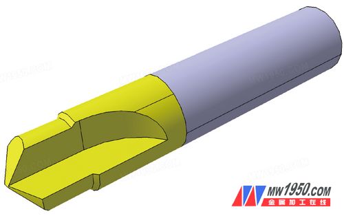
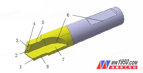
Improvements to the corners of the tool not only solve the problem of chipping, but also ensure cutting performance. Many drill bit grinding methods, such as grinding the transition edge, grinding the chisel edge, grinding the edge and grinding the chip flute, can not solve the chipping problem of the knife through the test. The theoretical basis of the turning tool gives us some inspiration. According to the powerful cutting tool and the roughing turning tool to prevent the cutting edge from chipping, the cutting edge design has a chamfered surface, and the width of the chamfered surface is very narrow. It can improve the strength of the cutting edge and increase the heat dissipation area. It is most suitable for the processing of rough cut forgings or intermittent surfaces. According to this idea, the chipping of the drill bit is improved, and the tool improvement is shown in Figure 2.

(a) before improvement

(b) after improvement
Fig. 2 The perspective view of the whole alloy drill bit 1. The main cutting edge 2. The chamfered surface after grinding 3. The main flank face 4. The angle of the tool nose 5. The minor flank face 6. The side of the chip flute 7. The rake face 8. Sub-cutting edge
After the cutter knife sharp corners at the main flank, flanks, and flutes formed in the side surface of the grind a chamfer surface, to improve innovations. Through the grinding test, it was finally determined that the width of the chamfered surface of the modified grinding was 4 mm, and the angle of the cutting edge was greater than 110°. Through the batch trial cutting of parts, there is no case of chipping. The improved tool not only greatly improved the heat dissipation area of the tool tip, but also increased the angle of the tool tip and enhanced the tool tip strength. Through the batch trial cutting of the product, the tool chipping phenomenon is completely solved, the tool processing cost is greatly reduced, the production cost is greatly reduced, and the production efficiency is improved.
Conclusion
The improved integral alloy drill bit can be applied to porous, easy-to-crush difficult-to-machine materials and cast iron materials, and can also be extended to metal processing industries. This improved method can be widely applied in the tool industry.
The improved integral alloy drill bit has broken the conventional grinding method of the drill bit, and is not common in the theory of the grinding bit. This improved method has a major breakthrough in the grinding method of the drill bit, and also provides a new way for the grinding method of the whole alloy bit. The idea has a promotion value in the tool industry.


